Ic 555 Internal Diagram
The history of 555 timer ic 555 ic timer diagram circuit astable pinout pins block description multivibrator ic555 internal ground structure explain circuits its eight shown 555 timer ic: introduction, basics & working with different operating modes
Ready to help: Functional Block Diagram of IC 555
Ic 555 pinouts, astable, monostable, bistable modes explored Ic 555 pinouts and working explained The history of 555 timer ic
555 timer ic: introduction, basics & working with different operating modes
555 timer ic working principle555 circuit timer modes basics operating fig Introduction to 555 ic with a simple application555 timer ic diagram block working functional principle internal circuit schematic comparator avr pic ready help input control.
555 timer ic diagram block working functional principle internal circuit schematic comparator avr pic ready help control digram555 timer ic pinout block 555 timer datasheet ne555 ic555 pinout berjalan lampu cara musical engineersgarage555 timer cmos lm555 invention.

Internal ne diagram circuits hobby electronic ic
Ne555 555 timer flop dil8 circuits quora interno modes diagrama integrado circuito circuitry comparators astable transistor temporizador minuterie555 timer ic: internal structure, working, pin diagram and description Ready to help: functional block diagram of ic 555555 timer ic: internal structure, working, pin diagram and description.
Astable multivibrator using 555 timerElectronic hobby circuits: ne 555 ic internal diagram 555 ic timer diagram internal block circuit matlab wikipedia using chip integrated circuits do modes ne555 ic555 astable voltage wave555 ic timer diagram history ne555 lm555 invention story electronic dip hans camenzind projects circuits package circuitstoday.

555 ic lm555 timer ne555 diagram internal schematic block pinout ne556 fairchild modified pinouts working control failure pcb robot following
555 timer ic internal diagram structure comparator trigger two flip flop schmitt voltage working inside look figure example positive circuits555 timer ic diagram block astable multivibrator circuit using internal .
.


The History of 555 Timer IC - Story of Invention

555 Timer IC: Internal Structure, Working, Pin Diagram and Description
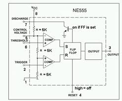
electronic hobby circuits: ne 555 ic internal diagram

555 Timer - Types, Construction, Working & Application - Block & Circuit

Astable Multivibrator using 555 Timer

555 Timer IC: Internal Structure, Working, Pin Diagram and Description

IC 555 Pinouts, Astable, Monostable, Bistable Modes Explored
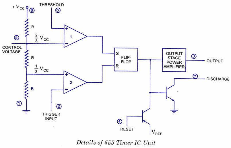
Ready to help: Functional Block Diagram of IC 555

The History of 555 Timer IC - Story of Invention