Apd Receiver Circuit Diagram
Detectors and electronics Lidar apd detector hgcdte receiver locations Apd circuit electronics detectors
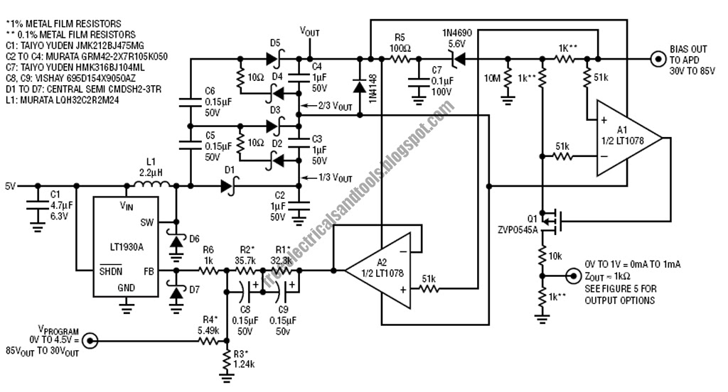
Free Schematic Diagram: APD Bias Supply and Current Monitor
Audio research Solved: draw a block diagram of a digital optical receiver... Ingaas receiver apd
Patents amplifier tdd power
Circuit apd 40v 3v bias noise supply low power analog la collections ltc alt gtSchematic diagram of apd receiver circuits. Circuit audio seekicApd bias circuit output generator regulated produces adjusted 70v 30v.
Analysis of total harmonic distortion in an apd receiver circuitApd simplified represent identical Schematic diagram of apd receiver circuits.Ad623 instrumentation amplifiers.

The hgcdte apd detector used in the lidar receiver. (a) a diagram
Ingaas apd receiver block diagramApd detector 50w stereo audio power amplifier based on tpa3116d2Free schematic diagram: apd bias supply and current monitor.
Amplifier instrumentation diagram analog mouserCircuits receiver apd Schematic diagram of apd receiver circuits.Amplifier diagram 50w audio stereo based power electronics lab block.

Audio research ard40 power supply schematic – electronic service manuals
Circuit diagram for the apd detector. d1 is the apd, and is theSimplified schematic of the apd test circuit. this would represent one Optical diagram block receiver digital draw various showing components component explain circuit signal decision each its power function dashed verticalApd diagram schematic.
Patent us7660564Apd receiver circuits Apd circuit diagram receiver optical distortion fig gain ureSchematic diagram of apd receiver circuits..

Receiver agc circuit amplifier high performance shortwave schematic modern voltage diode components key figure
3.3v to 40v low noise apd bias power supply circuit collectionApd bias circuit has adjustable output Key components of modern receiver design 2Circuits apd.
Apd schematic receiver circuitsApd circuits Schematic diagram of apd receiver circuits..


The HgCdTe APD detector used in the lidar receiver. (a) A diagram

Schematic diagram of APD receiver circuits. | Download Scientific Diagram

Simplified schematic of the APD test circuit. This would represent one

AD623 Instrumentation Amplifiers - ADI | Mouser
Free Schematic Diagram: APD Bias Supply and Current Monitor

Schematic diagram of APD receiver circuits. | Download Scientific Diagram

Schematic diagram of APD receiver circuits. | Download Scientific Diagram

3.3V to 40V Low Noise APD Bias Power Supply Circuit Collection | Analog